

Balancing Protocol
The aim of balancing is to apply adjustment of flow rates to achieve design requirements
1.0 Objectives of balancing
The aim of balancing is to apply a disciplined procedure of adjustment to water flow rates throughout a system to meet the particular requirements of the design. The balancing of the water flow rates should be carried out to specified tolerances.
2.0 Tolerances
It is the responsibility of the system designer to state acceptable tolerances for the balancing of flow rates for various sections of a particular system. In deciding on the appropriate tolerances to set, the designer should bear in mind that the cost of balancing procedure can increase significantly where close tolerances are specified.
Where the commissioning specialist considers that the tolerance levels required by the system designer are impractical he/she should formally advise the designer of this, clearly stating and explaining his/her reasons.
Where flow rate tolerances are not stated in the design parameters, the commissioning specialist should obtain the formal agreement of the system designer on the tolerance requirements before commencing balancing.
Both in heating and cooling, a good flow rate tolerance is +/- 10% of the design flow rate. A flow rate tolerance of +/- 5% of the design flow rate is very good but can be difficult to achieve in practice and can increase the cost of balancing. Tolerances above +/- 10% of the design flow rate should not be specified unless room comfort is of minor importance.
3.0 Preparation
Hydronic balancing is amongst the last operation before running the system. It has to be planned and achieved with all required care.
In order to guarantee a successful end result and to keep the cost under control as well, it is recommended to follow the following steps prior to the hydronic balancing procedure.
- Analyse the drawings of the HVAC system as built.
- Check the required conditions to achieve the balancing procedure.
- Make a first site inspection.
- Selection of the most appropriate balancing method.
3.1 Analyse the drawings of the HVAC system as built.
It is better to study the drawings of the system before going on site to make sure that the functions of the system are well understood, that the control loops are clearly identified and balancing valves placed where necessary. In order to avoid difficulties, it is advised to make a simplified sketch to show only what balancing concerns : pipe network, terminal units, pumps and balancing valves. In case of a four pipe distribution system, it is better to prepare two separate sketches (heating/cooling).
Those sketches allow to detect and to avoid future problems in the system as for example hydraulic interactivity, flow rates compatibility, useless balancing valves, etc.
It is time to check that all flow rates to be adjusted in each balancing valves are well specified and that the flow rate in a branch is the sum of the flow rates in the terminal units. Similarly, the flow rate in a riser should be the sum of the flow rates in the branches.
If the system is designed with a diversity factor, it is necessary to apply a special method which is described later.
3.2 Check the required conditions to achieve the balancing procedure
Prior to balancing procedure, following operation should be performed :
- Clean the filters and strainers.
- De-aerate the whole system.
- Pressurise the system.
- Check the pump characteristics (power supply, rotation and speed).
3.3 Make a first site inspection
A first site visit always allows to save time for balancing. A special focus should be put on following points:
- Identify the balancing valves : place, diameter, model, accessibility and identification label.
- Check that shut off valves are set on their normal positions (fully open or fully shut).
- Make sure that it is possible to fully open the control valve manually or thanks to the building management system.
- If differential pressure controllers are installed, make sure they are operating as designed.
3.4 Selection of the most appropriate balancing method
Methodology
The balancing procedure has to start with the terminals first. The terminals have to be balanced against themselves before any attempt is made for the branches. After all terminals from all branches within the same riser are balanced against themselves, the branches can be balanced against themselves. The last operation is to balance the risers againstbe checked. If possible the pump can be trimmed or its pump head can be set to an optimum value (variable speed pumps).
Balancing valves and measuring instrument tolerances
The balancing valve should have an accuracy which is better than the tolerance on flow rates the system designer has specified. This includes the mechanical accuracy as well as the reproducibility of any hand wheel position from any other position (hysteresis).
Balancing methods
The flow rate tolerances the designer has specified can be achieved only if a global balancing method is implemented. The choice of the method depends on the designer preference but can be guided by practical reasons.
- The Pre-setting Method consists of calculating the hand wheel position at the design stage. The validity of the calculation depends on how realistic is the calculation versus the real implementation of the system. This method is valid for small systems. Most of the case, it does not provide accurate flow rates in the terminals.
- The Compensated Method provides very accurate flow rates. The principle is the same as the Proportional Method but reliability is improved. Its main advantage is that each balancing valve should be accessed only once during the whole balancing procedure. Therefore, it is convenient if the balancing valves are not easily accessible. The main disadvantage is that three workers and two measuring instruments are required.
- Methods based on mathematical simulation of the system as built are the most reliable and cost effective. The principle consists of a few measurements of flow rates and pressure drops in the balancing valves. Then a computer calculation gives the final hand wheel setting. One worker with one measuring instrument can balance the whole system. This method has proven to be in average 25% cheaper than the others. The designer should specify the balancing valves and the compatible measuring instrument used as a computerised balancing instrument.
3.5 Preliminary design for balancing: hydraulic module
Whatever is the balancing method adopted by the commissioning specialist, the system designer should plan the balancing procedure at the design stage. All balancing methods are based on the hydraulic module concept. An hydraulic module is made of circuits piped in direct return with a main valve called the partner valve. In this respect, reverse return piping has to be avoided as no balancing procedure exists for this design.

The system should be designed so that it is possible to split it in hydraulic modules and hydraulic sub-modules. Such simple system is shown in the following figure:
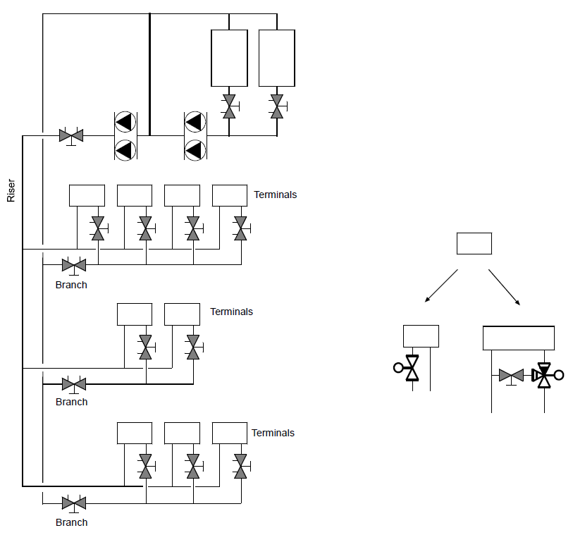

Design of the system so that it is possible to make modules.
3.6 Diversity factor
In case of diversity factor in the system, balancing valves can be used to simulate the diversity effect within a branch or a riser during the balancing procedure. The system is therefore balanced very close to the real operating condition.
4.0 Documentation
The documentation has to provide a full information about the balancing procedure. It has to include following information.
General data:
- Installation:
- Balancing method implemented:
- Balancing instrument used:
- Serial Number: Last calibration date:
- Name of the responsible of balancing:
- Company:
Data specific to the balancing valves:
- Identification of the valve:
- Design flow rate in the valve:
- Measured flow rate:
- Measured pressure drop:
- Position of the hand wheel:
This documentation will be used to verify the balancing job on site and as a basis for systematic analysis of the system when it is required.
Appendices 1 shows a typical balancing report.
5.0 Analysis of the Results
The balancing report can be used for trouble shooting in the system. The experience of the commissioning specialist should be predominant in this process. Nevertheless, some simple checking can be done:
- One balancing valve in each hydraulic module should have 3 kPa pressure drop. It is the balancing valve of the least favoured circuit (the index circuit). In case of identical circuits (e.g. a branch of fan coil units), the index circuit should be the last one. If not, it is a sign that some other circuit is blocked or a filter is clogged or a control valve refuses to open.
- If properly sized, the balancing valve should be opened above 50% of their maximum opening. If all balancing valves in an hydraulic module seems to be too much closed but one is normally opened, it is a sign that the pressure drop is abnormally high in the circuit with the normally opened balancing valve. This circuit should be checked and the module should be balanced again.
- Flow rates cannot be reached in all balancing valves in the hydraulic module. It is a sign that the available head is too low. Reasons are various but it can be a bypass somewhere in the system or a normally closed shut-off valve which is opened or half opened. If it happens in the main distribution, the pump should be visited and the pump curve should be checked.
6.0 Maintenance Recommendation
Balancing valves can be used for maintenance purpose at different levels : pumps, coil units, clogging detection and diagnostic of operations.
Pumps The pump curve can be easily checked with the balancing valve at the discharge of the pump. Pressure tests installed at the suction and discharge side of the pump allows pump head measurement and balancing valve at the discharge measures the flow rate. Some points from the pump curve can be easily checked and guarantees that the pump is operating as expected.
Coil units Balancing valves on the return of the coil units provide the possibility to measure the flow rate at any time and then help to check if the coils need to be cleaned or if the control valves work properly.
Clogging detection Balancing valves throughout the system allow to check the flow rate in the main branches and risers. If pipes or shut-off valves are clogged, it will be shown.
Diagnostic of operations Normal operation can be tracked. Balancing valves can be used to log the flow rate, the pressure as well as the water temperature at any point in the system at a minor extra cost.