

The TA Balance Method
The TA Balance Method is a computer program built in the balancing instrument CBIII with the same three main advantages of the Compensated Method plus the possibility for one man and one CBIII to balance an entire system:
These advantages are the following:
Staged commissioning: You can balance the plant in stages as construction goes on, without having to rebalance the entire building when it is completed.
Quicker commissioning: It reduces time consumption significantly since it is not necessary to measure the flows in all balancing valves and calculate all flow ratios. It also requires just one flow adjustment at each balancing valve.
Minimised pumping costs: When balancing is finished, you can read off the pump oversizing directly on the main balancing valve. The pump pressure may be reduced correspondingly. Frequently, large energy savings can be made, particularly in cooling plants.
One man and one instrument: After having done some measurements, the program calculates the correct settings of the balancing valves in order to achieve the desired flows.
The program assumes that the plant is divided into modules. Let us remember that a module is created of several circuits connected in direct return to the same supply and return pipes. Each circuit has its own balancing valve and the module has a common balancing valve called the Partner Valve.

1. Preparing the procedure
During the measurements, the differential pressure “ΔH”, at the inlet of the module, is supposed to be constant. The value of this “ΔH” is without importance unless it is insufficient to obtain good measurements. For this reason, the risers or modules not yet balanced, which can create big overflows, have to be isolated. To be sure that the pressure drops in the balancing valves will be sufficient to obtain a correct measurement, set the balancing valves on 50% opening (STAD = 2 turns), or at the precalculated positions if any. The Partner Valve of the module to be balanced must be fully open during the procedure.
The TA Balance Method demands that the valves be numbered according to the figure 1. The first valve after the Partner Valve must be number one, with following valves being numbered successively (See Fig 1). The Partner Valve is not numbered.
2. The procedure
Measure one module at the time. CBIII gives directions on the display of each step of the procedure. For each valve in the module, in any order, the following procedure is applied:
- Give the reference number, type, size and current position (e.g.1, STAD, DN20, 2 turns).
- Give the desired flow.
- A flow measurement is automatically performed.
- Shut the valve completely.
- A differential pressure measurement is automatically performed.
- Reopen the valve to its original position.
- When all balancing valves in the module have been measured, CBIII requires measuring the Δp across the Partner Valve fully shut.
When this procedure has been carried out, the CBIII calculates the correct setting for the balancing valves within the module. Adjust the balancing valves with these settings.
CBI'' has “discovered” the index circuit (the circuit requiring the highest differential pressure) and has given the concerned balancing valve the minimum pressure drop that is necessary to measure correctly the flow. This value is normally 3 kPa, but can be changed if you want. The settings of other balancing valves are calculated automatically to obtain a relative balancing of the elements in the module. These settings do no depend on the current differential pressure ΔH applied on the module.
At this moment, the correct flows are not yet achieved. This will happen when the Partner Valve has been adjusted to its correct flow. This operation is carried out later on in the procedure.
3. Balancing the modules of a riser between themselves
When all the modules in one riser have been balanced individually, these modules must be balanced between themselves. Each module is now looked upon as a circuit whose balancing valve is the Partner Valve in the module. The balancing procedure consists to calculate the setting of the Partner Valves of modules 1, 2 and 3 of the riser, using the TA Balance Method.
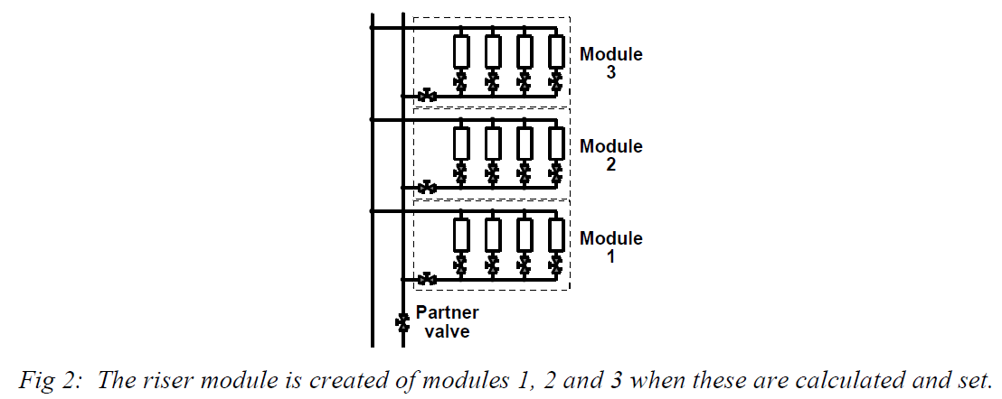

This riser module should now be measured and calculated in the same way as described earlier.
4. Balancing the risers between themselves
When all risers have been balanced individually, they constitute a module. The Partner Valve of this module is the main balancing valve associated with the pump.
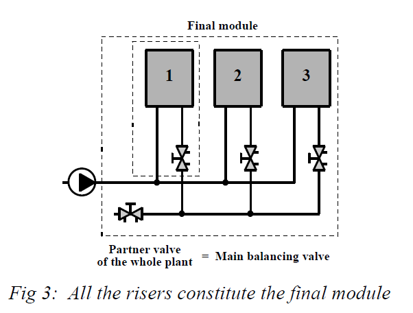

In this new module, the risers are balanced between themselves following the same procedure.
Finally, the total flow is adjusted with the main balancing valve. When this operation is completed, all circuits in the plant will have the desired flows. To verify this, flow measurements can be done on some balancing valves.
Printout via a PC provides a list of settings and verified data if these values have been stored.
All the overpressure is located in the main balancing valve. If this overpressure is important, the maximum pump speed can be reduced (variable speed pump), or with a constant speed pump, the impeller may be changed to reduce the pump head to save pumping costs. In some cases, the pump oversizing is so high that the pump is changed for a smaller one.
With a variable speed pump, the main balancing valve is not necessary. The maximum speed is adjusted to obtain the design flow in the Partner Valve of one of the risers. All the other flows will be automatically at design value.
Notes:
- During the measurements in one module, external disturbances (isolation of another riser …) have to be avoided. They may create some errors in the mathematical model elaborated by the CBI and some deviations in the flows obtained with the settings calculated.
- When measuring the differential pressure across a balancing valve fully shut, remember that the mechanical protection of the CBI will intervene automatically when this differential pressure is higher than 200 kPa. Above this value, a measurement cannot be done.
- TA Balance Method is generally the quickest balancing method, as it requires only one setter using a very simple procedure. However, in comparison with the Compensated Method, the setter has to go ones more at each balancing valve (to make the measurements). Consequently, if the balancing valves are very difficult to reach, the Compensated Method can be sometimes more economical.