IMI Hydronic, in collaboration with Enerbrain, worked to identify the best solution to ensuring minimum energy consumption and comfort optimization by implementing a TA-Smart based solution at one of its manufacturing sites.
The Project
As part of its Sustainability agenda, IMI Hydronic Engineering continuously investigates ways to reduce its carbon footprint while limiting its energy consumption in a highly volatile market. The company has invested a lot in improving its energy usage at its plant in Erwitte, Germany, by installing and using photovoltaic cells and wind farms. The Erwitte, management team wants to bolster the improvements. However, they need to understand where and how the energy is distributed with a granularity. To improve the entire production site system, an optimised hydronic solution was installed and piloted for a month; the positive results yielded for sitewide implementation.
IMI Hydronic collaborated with Enerbrain to identify the best solution ensuring minimum energy consumption and comfort optimisation; ≈45% of energy was saved during the month-long test and improved user comfort from 43% to 67%.
The Hydronic Challenge
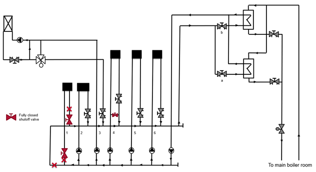
The building’s heating is produced in a central boiler room; two heat exchangers ensure the distribution from the primary to the secondary circuits. On the tertiary circuits, there are six consumers with different load and demand profiles. The primary consumer, an air handling unit /(AHU), has been identified and isolated; it accounts for 600kW and 80% of the load. The AHU is also responsible for the heating and air recirculation of the complete hall.
The team faced four main challenges:
System opacity: The team could not estimate how much energy was flowing and being consumed throughout
the system. They could not fix what they didn’t know.
Low flow controllability: The AHU and its heat exchangers have been initially oversized. In most cases, the load
was so small that the control valve was barely open, complicating the possibility of accurate control.
Load variability: Given the COVID pandemic, site production has continuously been adjusted to match demands and team availability. This led to complications in setting the correct heating cycles as needs were continuously changing.
System availability: The system update and pipework had to be carried out in a short period of time to ensure production was not disturbed for a long period of time.
Figure 1
The Solution
The solution was made up of two critical system updates:
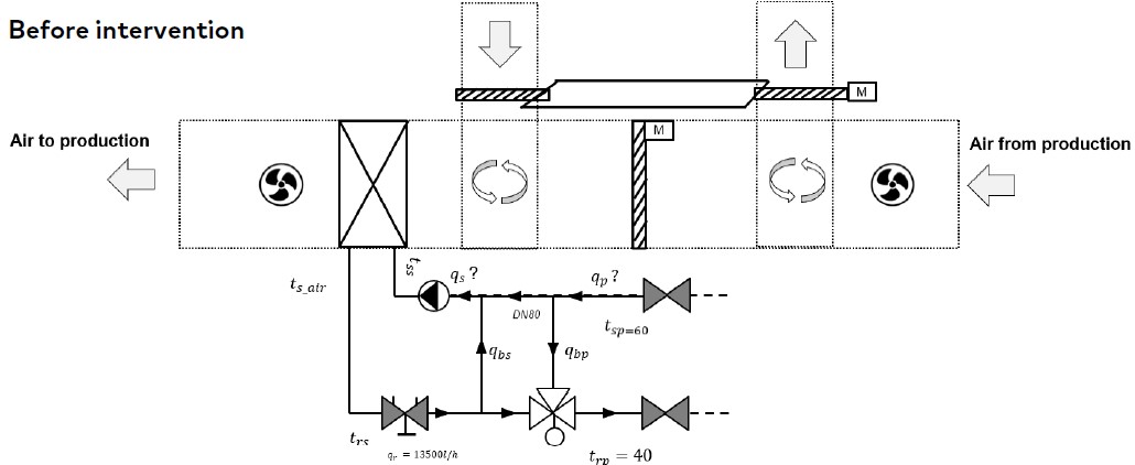
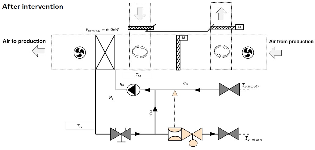
A TA-Smart DN80 has been installed in place of the 3-way mixing valve, and the by-pass has been closed, as shown in Figure 2. The valve continuously measures the energy flowing through the heat exchanger and controls the flow in the injection circuit. The flow, power, temperatures, and energy data are streamed every 15 seconds to HyCloud using a 4G Gateway. The TA-Smart valve breaks the system opacity by providing continuous actionable data and adjustments, ensuring excellent flow controllability. Its F1 length also enables a swift installation with limited pipework providing good system availability.
In collaboration with Enerbrain, four sensors measuring the relative humidity, temperature and CO2 levels have been installed in the production hall. The control system has also been upgraded to include a cloud control and visualisation solution. This system dynamically adjusts the setpoints from the valve, fans, and dampers according to the sensor’s measurement and historical data, leveraging advanced analytical algorithms. This upgrade contributed to breaking the system opacity by making data available in a consolidated manner. The system will also dynamically adjust the setpoint addressing system load variability.
Figure 2
The Process
To ensure that the solution worked properly, the installation and commissioning process was vital:
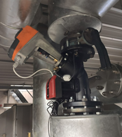
Installation: The TA-Smart replaced the 3-way valve. The 3rd pipe has been closed to convert the 3-way circuit to a 2-way injection circuit. A DN80 PN16 valve has been chosen to fit the existing piping. This was enabled by the outstanding control capabilities of the valve—the design flow accounting for 28% of the valve nominal flow. The TA-Smart is powered with a 24v AC supply and controlled using a 10vDC signal. The power supply and the input signals of the 3-way valve actuator were kept as originally installed. Ambient, battery-operated, sensors have been placed at strategic locations within the hall. The control system upgrade consisted of 3 main components placed between the original control panel and
the field device. The complete installation took one day and was performed by the maintenance team from the factory.
Comissioning: The valve has been parameterised using the HyTune app without requiring additional devices. The control mode has been set to Flow to ensure an EQM characteristic. The design flow has been adjusted to 13,500 l/h. A 4G gateway has been installed to stream data to HyCloud, as no bus or internal networks were available on-site.
Impact of TA-Smart
To assess the impact of the newly installed solution, two phases have been defined: one replicating the old system
and one for the new system; these two phases have been turned ON/OFF for two weeks:
Phase 1: After the solution installation, the TA-Smart has been set to position control to replicate the behaviour of the old 3-way valve, and the new control system has been turned off.
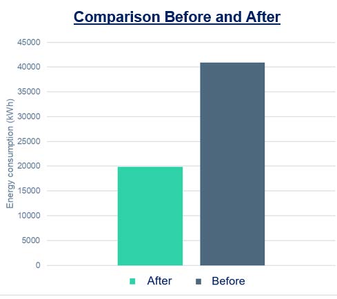
Phase 2: The TA-Smart has been set to flow control mode, and the algorithms have been switched ON. It’s possible to evaluate savings of thermal energy consumption of around 50%, as shown on Figure 3.Figure 3
It should be expected to have less energy savings during the summer and winter. Also, it is worth noting that the percentage of time in comfort has increased from 43% to 67% during the pilot period.
Proiecte de referință
College Antoine Courriere
Cuxac Cabardès, France
An eco-responsible renovation project of a high school in the south of France, ensuring optimal comfort for all users.
King Upkot Residential
Brussels, Belgium
-The King Upkot project is a new residential construction, in Brussels, Belgium. The building will be a student residence of more than 2,000 m2, made upfor 8 fl...
Royal Court of Appeals
The Royal Court of Appeal for Western Sweden is in central Gothenburg. The building is 6 stories tall and hosts 110 offices, 8 courtrooms and a library in 5,070 sqm. The building is ...
HyPerformance Upgrade in a High School, France
IMI Hydronic Engineering helped a High School in France upgrade its heating system to reduce energy costs and lower its carbon footprint, utilizing government funding opportunities.
...