

Bilanciamento di impianti tipici
Some system examples
Balancing of hydronic plants requires some specific conditions that will be analysed bases on some examples.
1. Variable flow system with balancing valves

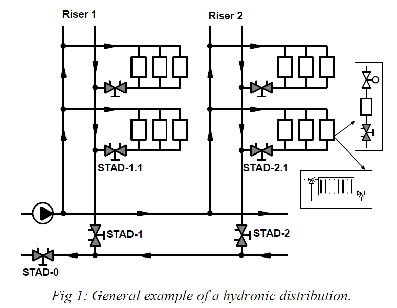
The system is divided in modules.
- STAD-1.1 is the Partner Valve of the first branch of the first riser.
- STAD-1 is the Partner Valve of the riser module and STAD-0 is the main Partner Valve.
When the terminal units are radiators, the thermostatic valves are preset based on a pressure drop of 10 kPa for design flow. Hydronic balancing is done before installing the thermostatic heads.
To balance such a system, we recommend the Compensated Method or the TA Balance Method. The main balancing valve STAD-0 shows the pump-oversizing and suitable action on the pump is made accordingly. If the pump is a variable speed pump, STAD-0 is not required; the speed of the pump is adjusted to obtain the design flow in the balancing valve of one of the risers.
2. System with BPV and balancing valves

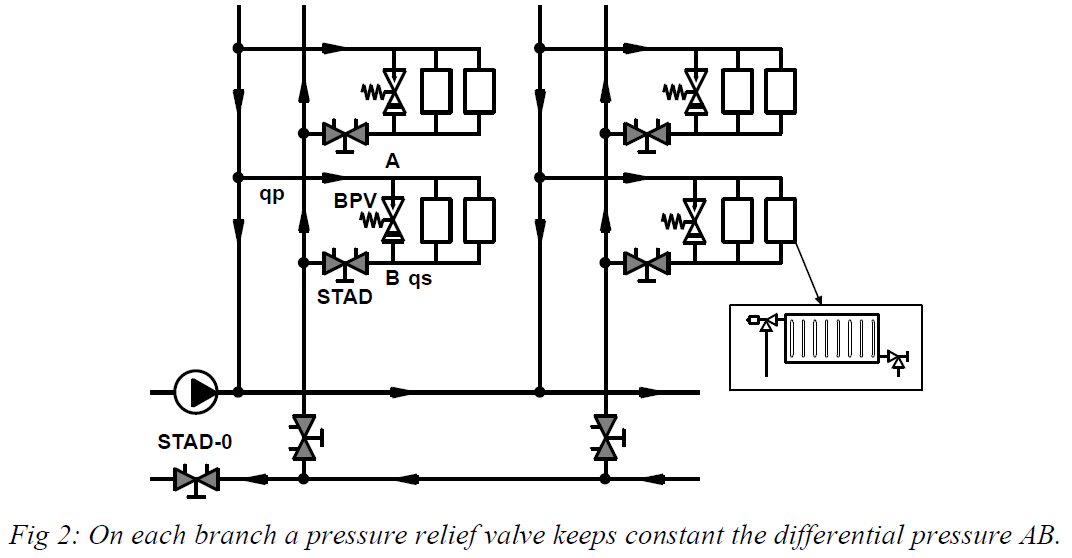
This system is mainly used in heating plants with radiators.
On each branch, serving several radiators or terminal units, the balancing valve is associated with a pressure relief valve BPV.
If some terminal control valves shut, the differential pressure AB has the tendency to increase. If this differential pressure increases above the set point of the BPV, the BPV starts to open. The increasing flow in the BPV creates a sufficient pressure drop in the balancing valve STAD to keep approximately constant the differential pressure across A and B. Without a balancing valve, the BPV, open or shut, will be submitted directly to the differential pressure between supply and return riser pipes. The BPV cannot alone stabilise the secondary differential pressure, it must be associated with a balancing valve.
The radiator valves are preset based on a pressure drop of 10 kPa for design flow. The plant is balanced as for figure 1 with all BPV fully shut. When the plant is fully balanced, the setting of the BPV is chosen equal to the 10 kPa adopted for the thermostatic valves plus 5 kPa, that means 15 kPa. There are other ways to set the BPV but the method suggested above is the simplest.
Example: The primary differential pressure available is 40 kPa. During the balancing procedure it was created a pressure drop of 27 kPa in the branch-balancing valve to obtain the correct water flow of 600 l/h in the branch. That means a differential pressure of 40 – 27 = 13 kPa between A and B in design condition. The radiator valves have been set for a differential pressure of 10 kPa, but to obtain the total correct flow, this differential pressure of 10 kPa has to be situated in the middle of the branch, so more than 10 kPa at its beginning (13 kPa).
Now let us consider that some thermostatic valves shut, decreasing the secondary flow qs. The table below gives some values showing the evolution of the flows and differential pressure.
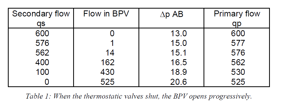

As the primary flow has only decreased from 600 l/h to 525 l/h, the primary differential pressure of 40 kPa remains practically unchanged.
The BPV starts to open when ΔpAB reaches the set point of 15 kPa. When all thermostatic valves are shut, the differential pressure ΔpAB reaches 20.6 kPa instead of more than 40 kPa without the BPV.
The main balancing valve STAD-0 shows the pump-oversizing and suitable action on the pump is made accordingly. If the pump is a variable speed pump, STAD-0 is not required; the speed of the pump is adjusted to obtain the design flow in the balancing valve of one of the risers.
3. System with STAP on each riser

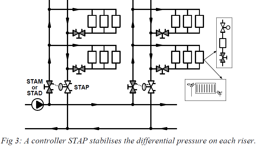
For large systems, the pump head may be too high or variable for some terminals. In this case, the differential pressure is stabilised at the bottom of each riser, at a suitable value, with a STAP differential controller.
Each riser is a module that can be considered independent from the others for the balancing procedure. Before starting the balancing of one riser, its STAP should be put out of function and fully open to be sure obtaining the required water flows during the balancing procedure. An easy way to do it is to shut the drain on the STAM or STAD in the supply and to purge the top of the membrane (Plug a CBI needle in the top of the STAP).
When the terminals are radiators, the thermostatic valves are first preset at design flow for a differential pressure of 10 kPa.
When each terminal has its own balancing valve, the terminals are balanced against themselves on each branch before balancing the branches against themselves with the Compensated Method or the TA Balance Method.
When a riser is balanced, the set point of its STAP is adjusted to obtain the design flow that can be measured with the STAM (STAD) valve situated at the bottom of this riser. The risers have not to be balanced between them.
Note:
- Some designers provide a pressure relief valve (BPV) at the end of each riser to obtain a minimum flow when all control valves are shut. Another method is to provide some terminal units with a three-way valve instead of a two-way control valve. Obtaining this minimum flow has several advantages: The flow of water in the pump does not drop below a minimum value.
- When the water flow is too low, the pipes heat losses cool down the water and the circuits remaining in function cannot deliver their full capacity if required, as their supply water temperature is too low. A minimum flow reduces this effect.
- If all the control valves shut, the differential pressure control valve STAP will also shut. All the return piping of this riser decreases in static pressure as the water is cooling down in a closed area. The differential pressure across the control valves will be so high that the control valve that reopens first will be extremely noisy. The minimum flow created avoids such a problem.
The setting of this BPV is done according to the following procedure:
- The STAP being in normal operation, all the branches of the riser are isolated.
- The STAM (STAD) is preset to obtain at least a pressure drop of 3 kPa for 25% of design flow.
- The BPV is set to obtain 25% of the riser design flow measurable at STAM (STAD).
- The STAM (STAD) is then reopened fully and all the branches are put again in normal function.
4. System with STAP on each branch

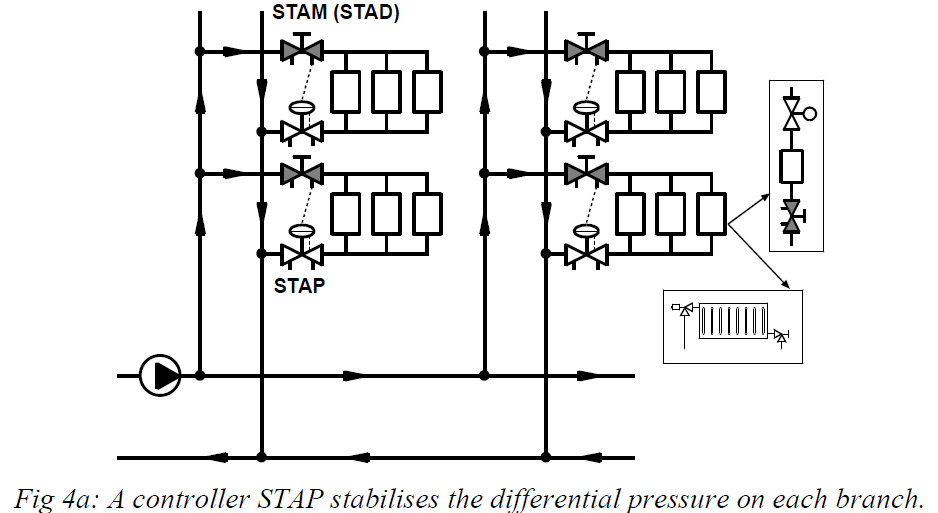
The differential pressure being stabilised on each branch, the terminals are supplied with a convenient differential pressure. Each branch is balanced independently of the others.
When the terminals are radiators, the thermostatic valves are first preset for a differential pressure of 10 kPa at design flow.
When each terminal has its own balancing valve, they are balanced between themselves using the Compensate method or the TA Balance Method.
When a branch is balanced, the set point of its STAP is adjusted to obtain the design flow that can be measured with the STAM (STAD) valve situated at the supply of the branch.
Some designers provide a pressure relief valve (BPV) at the end of each branch to obtain a minimum flow when all terminal control valves are shut. This gives simultaneously a minimum flow for the pump when all terminal control valves are shut. See the example hereafter.
It is not necessary to balance the branches between themselves and the risers between themselves.
Example: It is quite common to provide each apartment of a residential building with one STAP according to figure 4b. An On-Off control valve is associated with a room thermostat to control the ambience.
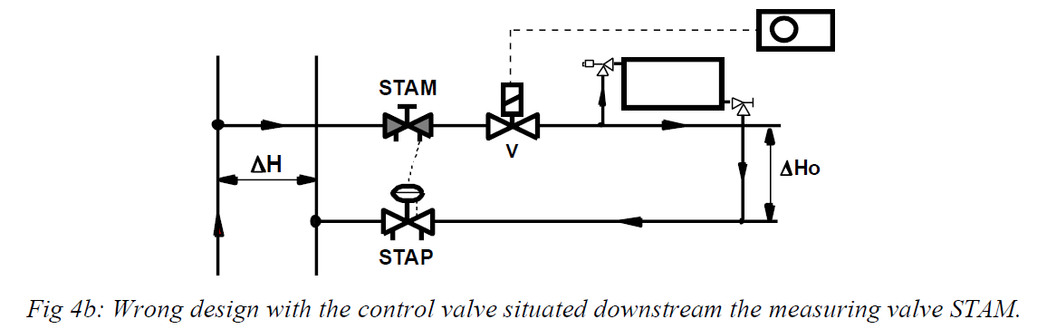

When the control valve is situated as in the figure 4b, the differential pressure ΔHo corresponds with the differential pressure obtained with the STAP minus the variable pressure drop in the control valve V. So ΔHo is not really well stabilised.
A second problem is the following: When the control valve “V” shuts, the STAP is submitted to the primary differential pressure ΔH and it also shuts. All the "secondary" circuit decreases in static pressure as the water is cooling down in a closed area. The Δp across valves "V" and STAP increases dramatically. When the control valve "V" starts to reopen, it can probably be very noisy due to cavitations in the valve “V”. This problem can be solved if the control valve is placed on the return, close to the STAP.
The correct design for the system is shown in figure 4c.
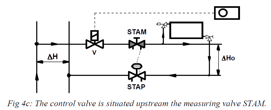

In figure 4c, when the control valve shuts, the differential pressure ΔHo drops to zero and the STAP opens fully. The secondary circuit remains in contact with the distribution and its static pressure remains unchanged, avoiding the problem discussed for figure 4b. Moreover, the differential pressure ΔHo is much bettered stabilised.
As we can see, a small change in the design of the system can modify dramatically its working conditions.
5. System with STAP on each control valve

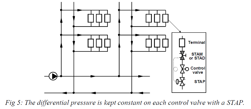
Each control valve is associated with a Δp controller STAP. From the control point of view, this is the best solution. Furthermore automatic balancing is obtained.
For each terminal successively, the control valve is fully open and the set point of the STAP is chosen to obtain the design flow. Each time the control valve is fully open, the design flow is obtained and the control valve is never oversized. As the differential pressure across the control valve is constant, its authority is close to one.
The balancing procedure is limited to the above description. Terminals, branches and risers are not to be balanced between them as this is obtained automatically.
What happens if only some control valves are combined with STAP and the others are not? In this case, we are back to figure 1 with balancing valves installed on branches and risers. The complete balancing is made with the STAPs fully open. Please note that a STAD is recommended in this case instead of a STAM. This STAD is used as a normal balancing valve during the balancing procedure. When the plant is balanced, the procedure for each STAP successively is the following:
- The STAD coupled with the STAP is reopen and preset to obtain at least 3 kPa for design flow.
- The set point of the STAP is adjusted to obtain the design flow across its control valve fully open, the flow being measured by means of the balancing valve STAD.
6. Constant flow distribution with secondary pumps

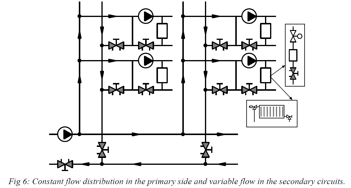
When there is just only one production unit, a constant flow distribution is the most suitable choice. The head of the primary pump has just to cover the pressure drops in the production unit and the primary distribution pipes. Each circuit is provided with a secondary pump.
To avoid interactivity between the primary pump and the secondary pumps, each circuit is provided with a bypass line.
Each circuit is balanced independently of the others.
The primary circuit is balanced separately as for system 1 with however the following remark. To avoid a short circuit with extreme overflows, it is recommended to put all balancing valves on the primary distribution to 50% opening before starting the balancing procedure.
7. Constant flow distribution with three way valves

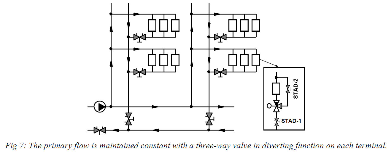
The balancing of this system is the same as for figure 1. For each three-way valve, a balancing valve STAD-1, in the constant flow, is essential for the balancing procedure. The balancing valve STAD-2 in the bypass has normally to create the same pressure drop as for the coil. In this case, the water flow will be the same when the three-way valve is fully open or fully shut. However, this balancing valve STAD2 is not necessary when the design pressure drop in the coil is lower than 25% of the design differential pressure available on the circuit.