Features & Benefits
Inline design
Inline flow allows high pressure drops without noise.
Pneumatic spring
Allows adjustable set-point from 0 to 16 bar.
Technical Information
Application:
Heating and cooling systems.
Function:
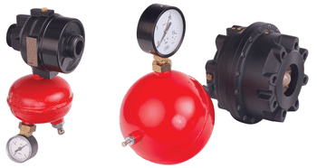
Inline pressure relief valve with pneumatic spring.
Opens at increasing inlet pressure.
Dimensions:
DN 15-125
Pressure class:
PN 25 or PN 16 (DN 100-125)
Max. differential pressure (ΔpV):
1 600 kPa = 16 bar
Setting range:
0-16 bar
Temperature:
Max. working temperature: 100°C
Min. working temperature: -10°C
Media:
Water or neutral fluids, water-glycol mixtures (0-57%).
Material:
Valve body: Ductile iron EN-GJS-400-15
Membranes and gaskets: NBR, EPDM
Surface treatment:
Electrophoretic painting.
Marking:
IMI TA, DN, PN, Kvs, material and flow direction arrow.
Connection:
DN 15-50: External threads according to ISO 228.
DN 65-125: Flanges according to EN-1092-2, type 21.
Articles
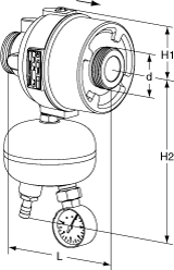
DN 15-50
External threads – Separate connections optional.
External thread according to ISO 228.

DN | d | L | H1 | H2 | Kvs | Kg | EAN | Article No | |
PN 25 | |||||||||
15/20 | G1 | 106 | 45 | 143 | 4 | 1,0 | 3831112505131 | 52 766-120 | |
25/32 | G1 1/4 | 125 | 55 | 161 | 12 | 1,7 | 3831112505148 | 52 766-125 | |
40/50 | G2 | 131 | 75 | 198 | 30 | 4,4 | 3831112505155 | 52 766-140 | |
Kvs = m3/h at a pressure drop of 1 bar and fully open valve.
→ = Flow direction
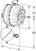
DN 65-125
Flanges – Do not need any separate connections.
Flanges according to EN-1092-2, type 21.

DN | D | L | H1 | H2 | Kvs | Kg | EAN | Article No | |
PN 25 (DN 65 and 80 also fit PN 16 flanges) | |||||||||
65 | 200 | 160 | 100 | 390 | 60 | 14 | 3831112500242 | 52 766-165 | |
80 | 200 | 160 | 100 | 390 | 60 | 14 | 3831112504110 | 52 766-180 | |
100 | 320 | 254 | 160 | 430 | 150 | 60 | 3831112525818 | 52 766-190 | |
125 | 320 | 254 | 160 | 430 | 150 | 60 | 3831112504523 | 52 766-191 | |
PN 16 | |||||||||
100 | 320 | 254 | 160 | 430 | 150 | 60 | 3831112505704 | 52 766-390 | |
125 | 320 | 254 | 160 | 430 | 150 | 60 | 3831112505711 | 52 766-391 | |
Kvs = m3/h at a pressure drop of 1 bar and fully open valve.
→ = Flow direction
Threads according to ISO 7. Swivelling nut.
With external thread
Threads according to ISO 7.
Swivelling nut.

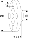
d1 | d2 | L1* | EAN | Article No |
G1 | R1/2 | 34 | 3831112500983 | 52 759-115 |
G1 | R3/4 | 40 | 3831112500990 | 52 759-120 |
G1 1/4 | R1 | 40 | 3831112501003 | 52 759-125 |
G1 1/4 | R1 1/4 | 45 | 3831112501010 | 52 759-132 |
G2 | R1 1/2 | 45 | 3831112503342 | 52 759-140 |
G2 | R2 | 50 | 3831112503472 | 52 759-150 |
Threads according to ISO 7-1. Swivelling nut.
With internal thread Rc
Threads according to ISO 7-1.
Swivelling nut.

d1 | d2 | L1* | EAN | Article No |
G1 | Rc1/2 | 26 | 3831112527454 | 52 751-301 |
G1 | Rc3/4 | 32 | 3831112527461 | 52 751-302 |
G1 1/4 | Rc1 | 47 | 3831112527478 | 52 751-303 |
G1 1/4 | Rc1 1/4 | 52 | 3831112527485 | 52 751-304 |
G2 | Rc1 1/2 | 52 | 3831112527492 | 52 751-305 |
G2 | Rc2 | 64,5 | 3831112527508 | 52 751-306 |
Swivelling nut
For welding
Swivelling nut

d1 | D | L1* | EAN | Article No |
G1 | 20,8 | 37 | 3831112500945 | 52 759-315 |
G1 | 26,3 | 42 | 3831112500952 | 52 759-320 |
G1 1/4 | 33,2 | 47 | 3831112500969 | 52 759-325 |
G1 1/4 | 40,9 | 47 | 3831112500976 | 52 759-332 |
G2 | 48,0 | 47 | 3831112501140 | 52 759-340 |
G2 | 60,0 | 52 | 3831112501294 | 52 759-350 |
Flange according to EN-1092-2:1997, type 16.
With flange
Flange according to EN-1092-2:1997, type 16.

d1 | d2 | D | L1* | EAN | Article No |
G1 | M12 | 95 | 10 | 3831112501065 | 52 759-515 |
G1 | M12 | 105 | 20 | 3831112501072 | 52 759-520 |
G1 1/4 | M12 | 115 | 5 | 3831112504318 | 52 759-525 |
G1 1/4 | M16 | 140 | 15 | 3831112501096 | 52 759-532 |
G2 | M16 | 150 | 5 | 3831112504325 | 52 759-540 |
G2 | M16 | 165 | 20 | 3831112501317 | 52 759-550 |
*) Fitting length (from the gasket surface to the end of the connection).
Threads according to ISO 228.
With internal thread
Threads according to ISO 228.

d1 | d2 | L1* | EAN | Article No |
G1 | G1/2 | 26 | 3831112501027 | 52 759-015 |
G1 | G3/4 | 32 | 3831112501034 | 52 759-020 |
G1 1/4 | G1 | 47 | 3831112501041 | 52 759-025 |
G1 1/4 | G1 1/4 | 52 | 3831112501058 | 52 759-032 |
G2 | G1 1/2 | 52 | 3831112503489 | 52 759-040 |
G2 | G2 | 64,5 | 3831112503205 | 52 759-050 |
Suitable when insulation is used.Stainless steel/EPDM/Brass.
Venting extension
Suitable when insulation is used.
Stainless steel/EPDM/Brass.

d | D | L | EAN | Article No |
M6 | 12 | 70 | 3831112531727 | 52 759-220 |
Brass/EPDM
Venting screw
Brass/EPDM

d | EAN | Article No |
M6 | 3831112527980 | 52 759-211 |


