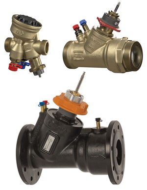
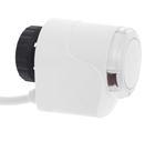
Features & Benefits
Precise temperature control
Provide uniquely shaped EQM characteristic for best modulating control.
Precise control
Uniquely shaped EQM characteristic provides an up to 6 times larger operating stroke than linear valves.
Quick hydronic balancing
Automatic flow limitation when actuator is fully open protects entire system against overflows.
Easy troubleshooting
Flow and differential pressure measuring helps to reduce pump consumption and provides all necessary data for system diagnostics.
Technical Information
Application:
Heating and cooling systems.
Functions:
Control EQM: DN 15 low flow, DN 10-200 normal flow
Control LIN: DN 65-200 high flow
Pre-setting (max. flow)
Differential pressure control
Measuring (ΔH, t, q)
Isolation (for use during system maintenance – see "Leakage rate")
Dimensions:
DN 10-200
Pressure class:
DN 10-50: PN 16
DN 65-200: PN 16, PN 25
Differential pressure (ΔpV):
Max. differential pressure (ΔpVmax):
DN 10-32: 600 kPa = 6 bar
DN 10-25: 400 kPa = 4 bar*
DN 40-50: 600 kPa = 6 bar
DN 65-200: 800 kPa = 8 bar
Min. differential pressure (ΔpVmin):
DN 10-20: 15 kPa = 0.15 bar
DN 25-32: 23 kPa = 0.23 bar
DN 40-200: 30 kPa = 0.30 bar
DN 65-80 HF: 45 kPa = 0.45 bar
DN 100-125 HF: 55 kPa = 0.55 bar
DN 150-200 HF: 60 kPa = 0.60 bar
(Valid for maximum setting, fully open. Other settings will require lower differential pressure, check with the software HySelect.)
ΔpVmax = The maximum allowed pressure drop over the valve to fulfill all stated performances.
ΔpVmin = The minimum recommended pressure drop over the valve, for proper differential pressure control.
*) With Δp insert in PPS.
HF = High flow
Flow range:
The flow (qmax) can be set within the range:
DN 10: 17 - 120 l/h
DN 15 LF: 38 - 230 l/h
DN 15: 92 - 480 l/h
DN 20: 200 - 975 l/h
DN 25: 340 - 1750 l/h
DN 32: 720 - 3600 l/h
DN 40: 1000 - 6500 l/h
DN 50: 2150 - 11200 l/h
DN 65: 4150 - 24100 l/h
DN 65 HF: 7460 - 36500 l/h
DN 80: 5850 - 37300 l/h
DN 80 HF: 9520 - 49000 l/h
DN 100: 11700 - 51700 l/h
DN 100 HF: 18000 - 75900 l/h
DN 125: 15000 - 77300 l/h
DN 125 HF: 23300 - 127000 l/h
DN 150: 26100 - 126000 l/h
DN 150 HF: 38800 - 190000 l/h
DN 200: 35000 - 209000 l/h
DN 200 HF: 73200 - 329000 l/h
qmax = l/h at each setting and fully open valve plug.
LF = Low flow
HF = High flow
Temperature:
DN 10-32:
Max. working temperature: 120°C
Min. working temperature: -20°C
DN 10-25 with Δp insert in PPS, DN 40-50:
Max. working temperature: 90°C
Min. working temperature: -10°C
DN 65-200:
Max. working temperature: 120°C
Min. working temperature: -10°C
Media:
Water or neutral fluids, water-glycol mixtures (0-57%).
Lift:
DN 10-20: 4 mm
DN 25-32: 6,5 mm
DN 40-50: 15 mm
DN 65-125: 20 mm
DN 150: 30 mm
DN 200: 32,5 mm
Rangeability:
DN 10 - 15 LF: >50
DN 15 - 32: >75
DN 40 - 80: >125
DN 100 - 150: >150
DN 100 - 150 HF: >125
DN 200: >125
DN 200 HF: >125
Leakage rate:
Leakage flow ≤ 0.01% of max. qmax (max. setting) and correct flow direction. (Class IV according to EN 60534-4).
Characteristics:
Independent shaped EQM.
DN 65-200 HF: Linear.
Material:
DN 10-32:
Valve body: AMETAL®
Valve insert: AMETAL® and PPS
Valve plug: Brass CW724R (CuZn21Si3P)
Spindle: Stainless steel
Spindle seal: EPDM O-ring
Δp insert: PPS and AMETAL® or PPS
Membrane: EPDM
Springs: Stainless steel
O-rings: EPDM
DN 40-50:
Valve body: AMETAL®
Valve insert: AMETAL®
Valve plug: AMETAL® and PTFE
Spindle: Stainless steel
Spindle seal: EPDM O-ring
Δp insert: PPS
Membrane: EPDM
Springs: Stainless steel
O-rings: EPDM
DN 65-200:
Valve body: Ductile iron EN-GJS-400-15
Valve insert: Ductile iron EN-GJS-400-15 and brass
Valve plug: Stainless steel and EPDM O-ring
Valve seat: Aluminium bronze
Spindle: Stainless steel
Spindle seal: EPDM
Δp insert: Ductile iron EN-GJS-400-15, stainless steel and brass.
Membrane: Reinforced EPDM, DN 200 EPDM
Springs: Stainless steel
O-rings: EPDM
AMETAL® is the dezincification resistant alloy of IMI Hydronic Engineering.
Surface treatment:
DN 10-50: Non treated
DN 65-200: Electrophoretic painting
Connection:
DN 10-50: External thread according to ISO 228.
DN 65-200: Flanges according to EN-1092-2, type 21. Face to face length according to EN 558, series 1.
Connection to actuator:
DN 10-32: M30x1.5, push
DN 40-50: M30x1.5, push/pull
DN 65-200: 2xM8, push/pull
Actuators:
DN 10-20:
TA-Slider 160, EMO TM, TA-TRI.
DN 25-32:
TA-Slider 160, TA-TRI, TA-MC50-C*.
DN 40-50:
TA-Slider 500, TA-Slider 750*.
DN 65-125:
TA-Slider 750.
DN 100-125 HF:
TA-Slider 750 ΔpV ≤ 4 bar, TA-Slider 1600 ΔpV ≤ 8 bar.
DN 150-200, DN 150-200 HF:
TA-Slider 1600.
TA-Slider 160, 500, 750 and 1600 also available with fail-safe function.
*) Adapter to be ordered separately, see "Adapters for actuators".
For more details on actuators, see separate technical leaflets.
Certification and directives:
DN 65-200: CE, EAC, UKCA
Articles
DN 65-200 – Temperature -10 – +120°C, ΔpV max. 800 kPa
Flanges according to EN 1092-2, type 21.
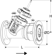
PN 16
DN | Number of bolt holes | ØD | L | H | qmax [m3/h] | Kg | EAN | Article No |
65 | 4 | 185 | 290 | 249 | 24,1 | 18 | 3831112533271 | 322021-11001 |
65 HF | 4 | 185 | 290 | 249 | 36,5 | 18 | 5902276810213 | 322021-11008 |
80 | 8 | 200 | 310 | 260 | 37,3 | 22 | 3831112533318 | 322021-11101 |
80 HF | 8 | 200 | 310 | 260 | 49,0 | 22 | 5902276810251 | 322021-11109 |
100 | 8 | 220 | 350 | 280 | 51,7 | 33 | 3831112535527 | 322021-11200 |
100 HF | 8 | 220 | 350 | 280 | 75,9 | 33 | 3831112535565 | 322021-11203 |
125 | 8 | 250 | 400 | 287 | 77,3 | 45 | 3831112535602 | 322021-11300 |
125 HF | 8 | 250 | 400 | 287 | 127 | 45 | 3831112535640 | 322021-11303 |
150 | 8 | 285 | 480 | 357 | 126 | 75 | 3831112535701 | 322021-11400 |
150 HF | 8 | 285 | 480 | 357 | 190 | 75 | 3831112535749 | 322021-11403 |
200 | 12 | 340 | 600 | 391 | 209 | 136 | 5902276819810 | 322021-11500 |
200 HF | 12 | 340 | 600 | 391 | 329 | 136 | 5902276819827 | 322021-11503 |
PN 25
DN | Number of bolt holes | ØD | L | H | qmax [m3/h] | Kg | EAN | Article No |
65 | 8 | 185 | 290 | 249 | 24,1 | 18 | 3831112533288 | 322021-11002 |
65 HF | 8 | 185 | 290 | 249 | 36,5 | 18 | 5902276810220 | 322021-11009 |
80 | 8 | 200 | 310 | 260 | 37,3 | 22 | 3831112533325 | 322021-11102 |
80 HF | 8 | 200 | 310 | 260 | 49,0 | 22 | 5902276810268 | 322021-11110 |
100 | 8 | 235 | 350 | 280 | 51,7 | 34 | 3831112535534 | 322021-11201 |
100 HF | 8 | 235 | 350 | 280 | 75,9 | 34 | 3831112535572 | 322021-11204 |
125 | 8 | 270 | 400 | 287 | 77,3 | 47 | 3831112535619 | 322021-11301 |
125 HF | 8 | 270 | 400 | 287 | 127 | 47 | 3831112535657 | 322021-11304 |
150 | 8 | 300 | 480 | 357 | 126 | 77 | 3831112535718 | 322021-11401 |
150 HF | 8 | 300 | 480 | 357 | 190 | 77 | 3831112535756 | 322021-11404 |
200 | 12 | 360 | 600 | 391 | 209 | 136 | 5902276819834 | 322021-11501 |
200 HF | 12 | 360 | 600 | 391 | 329 | 136 | 5902276819841 | 322021-11504 |
HF = High flow
*) Connection to actuator.
→ = Flow direction
External threads according to ISO 228.
DN 40-50 HP – Temperature -10 – +90°C, ΔpV max. 600 kPa
External threads according to ISO 228.
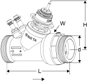
DN | d | L | H | W | qmax [l/h] | Kg | EAN | Article No |
40 | G2 | 187 | 132 | 88 | 6500 | 3,5 | 5902276821769 | 52 164-440 |
50 | G2 1/2 | 196 | 135 | 88 | 11200 | 3,9 | 5902276821776 | 52 164-450 |
*) Connection to actuator.
→ = Flow direction
External threads according to ISO 228.
DN 10-25 – Temperature -10 – +90°C, ΔpV max. 400 kPa
External threads according to ISO 228.
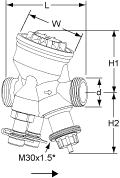
DN | d | L | H1 | H2 | W | qmax [l/h] | Kg | EAN | Article No |
10 | G1/2 | 74 | 55 | 55 | 54 | 120 | 0,53 | 7318794040304 | 52 164-310 |
15 LF | G3/4 | 74 | 55 | 55 | 54 | 230 | 0,54 | 5902276821424 | 52 164-314 |
15 | G3/4 | 74 | 55 | 55 | 54 | 480 | 0,54 | 7318794027008 | 52 164-315 |
20 | G1 | 85 | 64 | 55 | 64 | 975 | 0,69 | 7318794027107 | 52 164-320 |
25 | G1 1/4 | 93 | 64 | 67 | 64 | 1750 | 0,79 | 7318794027206 | 52 164-325 |
→ = Flow direction
LF = Low flow
*) Connection to actuator.
External threads according to ISO 228.
DN 10-32 HP – Temperature -20 – +120°C, ΔpV max. 600 kPa
External threads according to ISO 228.
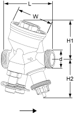
DN | d | L | H1 | H2 | W | qmax [l/h] | Kg | EAN | Article No |
10 | G1/2 | 74 | 55 | 55 | 54 | 120 | 0,59 | 5902276821431 | 52 164-410 |
15 LF | G3/4 | 74 | 55 | 55 | 54 | 230 | 0,60 | 5902276821448 | 52 164-414 |
15 | G3/4 | 74 | 55 | 55 | 54 | 480 | 0,60 | 7318794033405 | 52 164-415 |
20 | G1 | 85 | 64 | 55 | 64 | 975 | 0,75 | 7318794033504 | 52 164-420 |
25 | G1 1/4 | 93 | 64 | 67 | 64 | 1750 | 0,90 | 7318794033603 | 52 164-425 |
32 | G1 1/2 | 117 | 78 | 70 | 78 | 3600 | 1,5 | 7318794027305 | 52 164-332 |
→ = Flow direction
LF = Low flow
*) Connection to actuator.
Threads according to ISO 7-1. Swivelling nut.
With External thread
Threads according to ISO 7-1.
Swivelling nut.
Brass

For DN | D | D1 | L* | EAN | Article No |
10 | - | - | - | - | - |
15 | G3/4 | R1/2 | 29 | 4024052516612 | 0601-02.350 |
20 | G1 | R3/4 | 32,5 | 4024052516810 | 0601-03.350 |
25 | G1 1/4 | R1 | 35 | 4024052517015 | 0601-04.350 |
32 | G1 1/2 | R1 1/4 | 38,5 | 4024052517213 | 0601-05.350 |
Compression connection
Support bushes shall be used, for more information see catalogue leaflet FPL.
Should not be used with PEX pipes.
Brass/AMETAL®
Chrome plated

For DN | D | Pipe Ø | L** | EAN | Article No |
10 | G1/2 | 8 | 16 | 7318793620002 | 53 319-208 |
10 | G1/2 | 10 | 17 | 7318793620101 | 53 319-210 |
10 | G1/2 | 12 | 17 | 7318793620200 | 53 319-212 |
10 | G1/2 | 15 | 20 | 7318793620309 | 53 319-215 |
10 | G1/2 | 16 | 25 | 7318793620408 | 53 319-216 |
15 | G3/4 | 15 | 27 | 7318793705006 | 53 319-615 |
15 | G3/4 | 18 | 27 | 7318793705105 | 53 319-618 |
15 | G3/4 | 22 | 27 | 7318793705204 | 53 319-622 |
*) Fitting length (from the gasket surface to the end of the connection).
**) Over all length L refers to unassembled coupling.
Threads according to ISO 228.
With internal thread
Threads according to ISO 228.
Thread length according to ISO 7-1.
Swivelling nut.
Brass/AMETAL®

For DN | D | D1 | L* | EAN | Article No |
10 | G1/2 | G3/8 | 21 | 7318794016804 | 52 163-010 |
15 | G3/4 | G1/2 | 21 | 7318794016903 | 52 163-015 |
20 | G1 | G3/4 | 23 | 7318794017009 | 52 163-020 |
25 | G1 1/4 | G1 | 23 | 7318794017108 | 52 163-025 |
32 | G1 1/2 | G1 1/4 | 31 | 7318794017207 | 52 163-032 |
40 | G2 | G1 1/2 | 30 | 7318794032705 | 52 163-040 |
50 | G2 1/2 | G2 | 32 | 7318794032804 | 52 163-050 |
Swivelling nut.
Welding connection
Swivelling nut.
Brass/Steel 1.0045 (EN 10025-2)

For DN | D | Pipe Ø | L* | EAN | Article No |
10 | G1/2 | 10 | 30 | 7318792748400 | 52 009-010 |
15 | G3/4 | 15 | 36 | 7318792748509 | 52 009-015 |
20 | G1 | 20 | 40 | 7318792748608 | 52 009-020 |
25 | G1 1/4 | 25 | 40 | 7318792748707 | 52 009-025 |
32 | G1 1/2 | 32 | 40 | 7318792748806 | 52 009-032 |
40 | G2 | 40 | 45 | 7318792748905 | 52 009-040 |
50 | G2 1/2 | 50 | 50 | 7318792749001 | 52 009-050 |
For connection with press coupling. Swivelling nut.
Connection with smooth end
For connection with press coupling.
Swivelling nut.
Brass/AMETAL®

For DN | D | Pipe Ø | L* | EAN | Article No |
10 | G1/2 | 12 | 35 | 7318793810502 | 52 009-312 |
15 | G3/4 | 15 | 39 | 7318793810601 | 52 009-315 |
20 | G1 | 18 | 44 | 7318793810700 | 52 009-318 |
20 | G1 | 22 | 48 | 7318793810809 | 52 009-322 |
25 | G1 1/4 | 28 | 53 | 7318793810908 | 52 009-328 |
32 | G1 1/2 | 35 | 59 | 7318793811004 | 52 009-335 |
40 | G2 | 42 | 70 | 7318793811103 | 52 009-342 |
50 | G2 1/2 | 54 | 80 | 7318793811202 | 52 009-354 |
Swivelling nut.
Soldering connection
Swivelling nut.
Brass/gunmetal CC491K (EN 1982)

For DN | D | Pipe Ø | L* | EAN | Article No |
10 | G1/2 | 10 | 10 | 7318792749100 | 52 009-510 |
10 | G1/2 | 12 | 11 | 7318792749209 | 52 009-512 |
15 | G3/4 | 15 | 13 | 7318792749308 | 52 009-515 |
15 | G3/4 | 16 | 13 | 7318792749407 | 52 009-516 |
20 | G1 | 18 | 15 | 7318792749506 | 52 009-518 |
20 | G1 | 22 | 18 | 7318792749605 | 52 009-522 |
25 | G1 1/4 | 28 | 21 | 7318792749704 | 52 009-528 |
32 | G1 1/2 | 35 | 26 | 7318792749803 | 52 009-535 |
40 | G2 | 42 | 30 | 7318792749902 | 52 009-542 |
50 | G2 1/2 | 54 | 35 | 7318792750007 | 52 009-554 |
Adapters to other combinations of valve and recommended actuator are NOT needed.
Adapters
Adapters to other combinations of valve and recommended actuator are NOT needed.
For actuator | For DN | EAN | Article No |
TA-MC50-C | 25-32 | 3831112533851 | 322042-10700 |
TA-Slider 750 | 40-50 | 5902276819308 | 322042-80800 |
Suitable when insulation is used.
Venting extension
Suitable when insulation is used.
AMETAL®
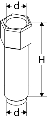
For DN | D | d | H | EAN | Article No |
40-50 | M10x1 | M10x1 | 32 | 7318794033702 | 52 164-301 |
Spare part.
Venting plug
Spare part.
AMETAL®
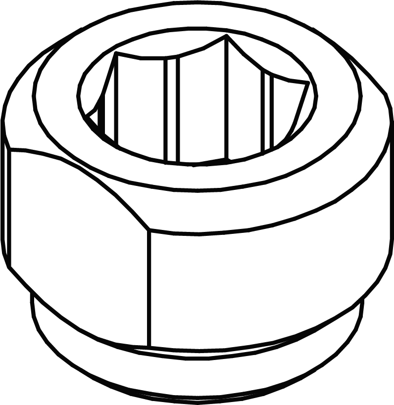
For DN | EAN | Article No |
40-50 | 7318794033801 | 52 164-302 |
Can be installed without draining of the system.AMETAL®/Stainless steel/EPDM
Measuring point, extension 60 mm
Can be installed without draining of the system.
AMETAL®/Stainless steel/EPDM
For all dimensions.
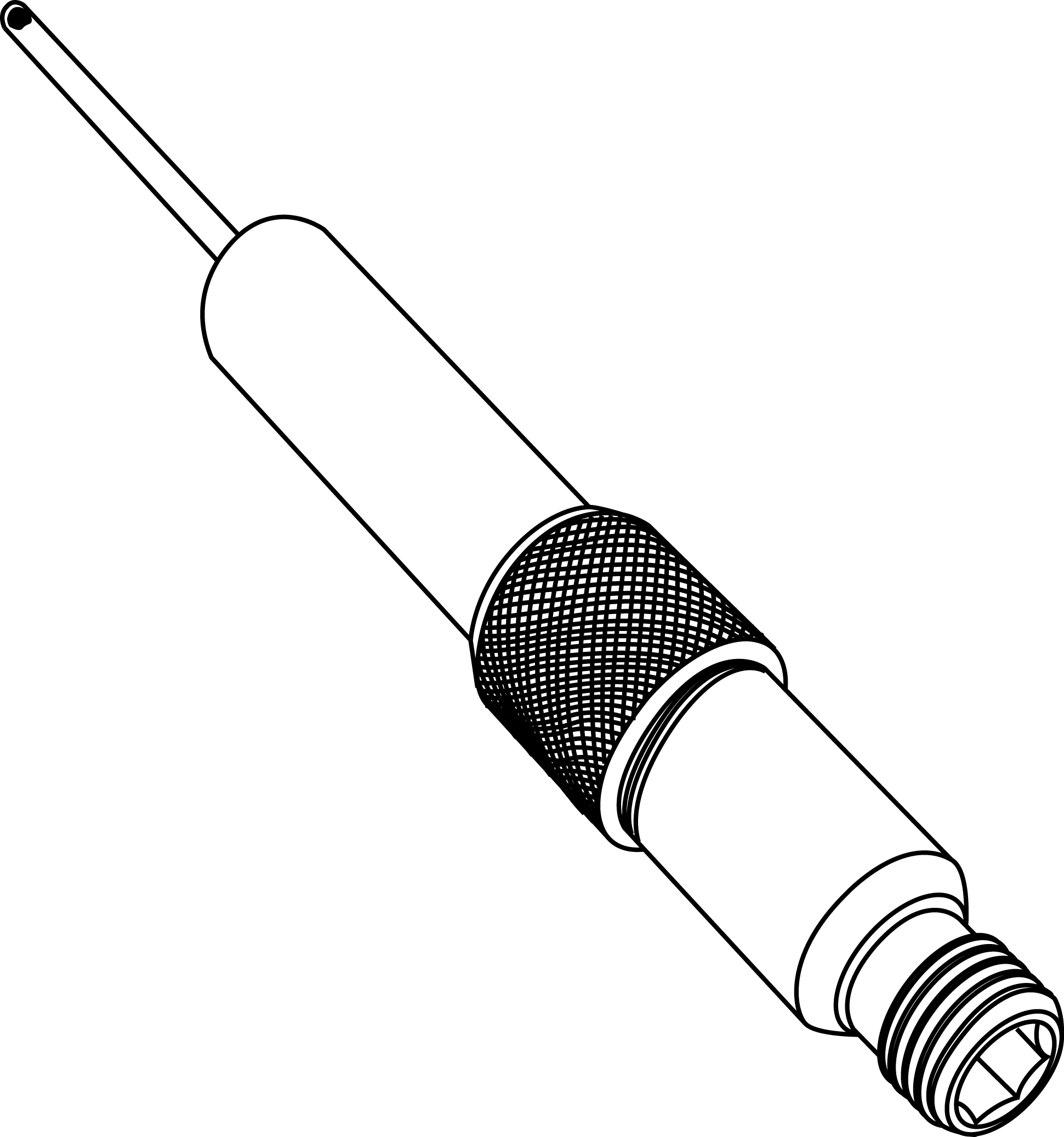
L | EAN | Article No |
60 | 7318792812804 | 52 179-006 |
Set containing plastic cover and locking ring for valves with connection M30x1.5 to thermostatic head/actuator. Prevents manipulation of setting.
Tamper proof cover
Set containing plastic cover and locking ring for valves with connection M30x1.5 to thermostatic head/actuator.
Prevents manipulation of setting.
Suitable for DN 10-32.
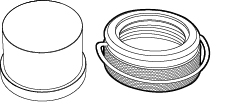
EAN | Article No |
7318794030206 | 52 164-100 |
For TA-COMPACT-P/-DP, TA-Modulator (DN 10-20), TBV-C/-CM.
Protection cap
For TA-COMPACT-P/-DP, TA-Modulator (DN 10-20), TBV-C/-CM.

Colour | EAN | Article No |
Red | 7318793961105 | 52 143-100 |
For better grip when presetting.For TA-COMPACT-P/-DP and TA-Modulator (DN 10-32).
Grip for setting wheel, optional
For better grip when presetting.
For TA-COMPACT-P/-DP and TA-Modulator (DN 10-32).
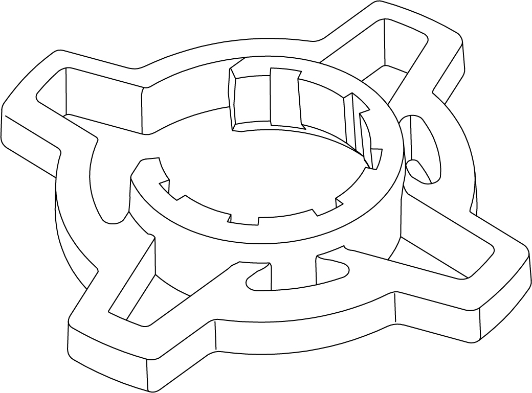
Colour | EAN | Article No |
Orange | 7318794040502 | 52 164-950 |
Recommended together with the insulation to minimize the risk of condensation at the valve-actuator interface.M30x1,5.
Spindle extension for DN 10-20
Recommended together with the insulation to minimize the risk of condensation at the valve-actuator interface.
M30x1,5.
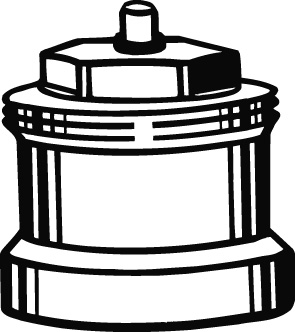
Type | L | EAN | Article No |
Plastic, black | 30 | 4024052165018 | 2002-30.700 |
For heating/comfort cooling.Material: EPP.Fire class: DN 10-32: E (EN 13501-1), B2 (DIN 4102).DN 40-50: F (EN 13501-1), B3 (DIN 4102).
Insulation
For heating/comfort cooling.
Material: EPP.
Fire class:
DN 10-32: E (EN 13501-1), B2 (DIN 4102).
DN 40-50: F (EN 13501-1), B3 (DIN 4102).
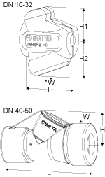
For DN | L | H | H1 | H2 | W | EAN | Article No |
10-15 | 100 | - | 61 | 71 | 84 | 7318794027404 | 52 164-901 |
20 | 118 | - | 67 | 79 | 90 | 7318794027503 | 52 164-902 |
25 | 127 | - | 71 | 84 | 104 | 7318794027602 | 52 164-903 |
32 | 154 | - | 85 | 99 | 124 | 7318794027701 | 52 164-904 |
40 | 277 | 105 | - | - | 131 | 7318794030800 | 52 164-905 |
50 | 277 | 105 | - | - | 131 | 7318794030909 | 52 164-906 |
Photos

520090xx
Select a format Download
32202111101
Select a format Download
32202111102
Select a format Download
52164901-904_persp
Select a format Download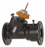
32202111001
Select a format Download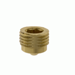
52164302
Select a format Download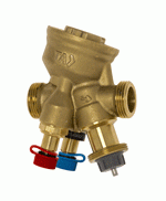
TA-Modulator_DN15_metal_persp
Select a format Download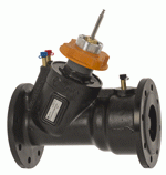
32202111002
Select a format Download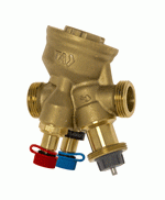
52164332
Select a format Download
060102350
Select a format Download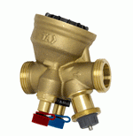
52164320
Select a format Download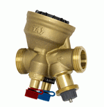
TA-MODULATOR_persp_kat_w_path
Select a format Download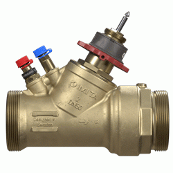
TA-Modulator_DN50
Select a format Download
52164340
Select a format Download
52163040
Select a format Download
52163015
Select a format Download
52164100
Select a format Download
52164301
Select a format Download
52164315
Select a format Download
520093xx
Select a format Download
TA-Modulator_DN80_persp
Select a format Download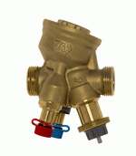
TA-Modulator_DN15_metal
Select a format Download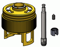
32204280800
Select a format Download
53319xxx
Select a format Download
52009515
Select a format Download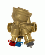
52164420
Select a format Download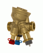
52164415
Select a format Download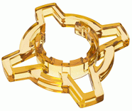
52164950
Select a format Download
TA-Modulator_DN50_persp
Select a format Download
52164425
Select a format Download
52164325
Select a format Download
52164350
Select a format Download
32204210700
Select a format Download
52164901-904
Select a format Download
TA-Modulator_DN80
Select a format Download
52143100
Select a format Download